Euripus Strait old steel drawbridge
(By Dimitris Tolis - Structural Engineer)
BACKGROUND
The steel drawbridge of Euripus is an original construction, a typical example of the ingenuity of Greek engineers who designed it. The process for constructing already begun in 1960 and since then this project is an important element of the city of Chalκis while until sometime (when was launched in the new high bridge) the single access point to Evia from the mainland. I will not attempt here to discuss any historical background since there is already a very eloquently written one.
In this link (Greek text) you will find a report prepared by my professor in Reinforced Concrete at the National Technical University of Athens Th. Tassios (whom I honor, as well as too many other colleagues of mine, and is one of the most key people I have had the luck to meet at the University) who wrote it on the occasion of an event prepared by the Technical Chamber of Greece in 2008.
THE RENOVATION
The renovation of the bridge that took place between the years 1995-8 seemed to many people that was mostly a replacement of the existing wooden deck by asphalt layer and the painting of steel elements. But was it?
In 1995 the contractor KOROTZIS SA was awarded to the renovation of the electromechanical installations of the bridge, the repair of the railings, the painting of the steel members and the replacement the wooden deck with an asphalt pavement. In charge of the project, by the contractor, was at Mr. K. Stoubos, a mechanical engineer, who found that according the contract design the replacement of the deck contributed very little to the increase of the permanent loads of the bridge and therefore the contract design omitted the revision of forces in the existing structure. But unfortunately this conclusion was based on a numerical calculation error of one significant digit, i.e. the loads were calculated 10 times less!
After this finding
the contractor hired as consultants, in agreement with the relevant authority, Mr. J Malliaris (whom I also honor, having the great chance to meet him in the early years of my professional career) and myself in order to review the existing structure, the new loads, and the design of the necessary reinforcements.
Alongside the relevant authority had set as a condition, for funding the emerging project, the compliance with the newer standard requirements (i.e. DIN 1072-1985, DIN 18800-1990 and the Greek Earthquake Design standard along with the current special guidance for the design of bridges) .
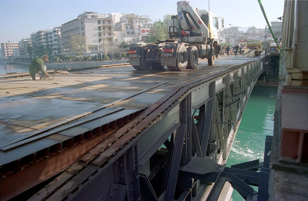
At the site visit, under the above assignment, I found that the bridge, under very heavy loads (trucks loaded with steel rolls etc) and other very heavy traffic that were using the bridge at that time, was enormously oscillating both vertically and horizontally creating among other things and a lot of noise.
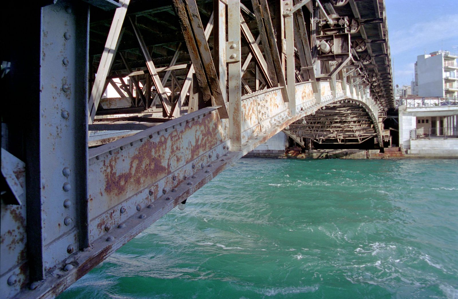
It is characteristic to mention that when the bridge was loaded with a high load about the position of the connecting joint, in the middle of the span (the bridge consists of two cantilevers connected at midspan), a step of some centimeters was created between the two parts of the bridge, that after the passage of the truck from above the joint abruptly was changing direction creating a loud noise.
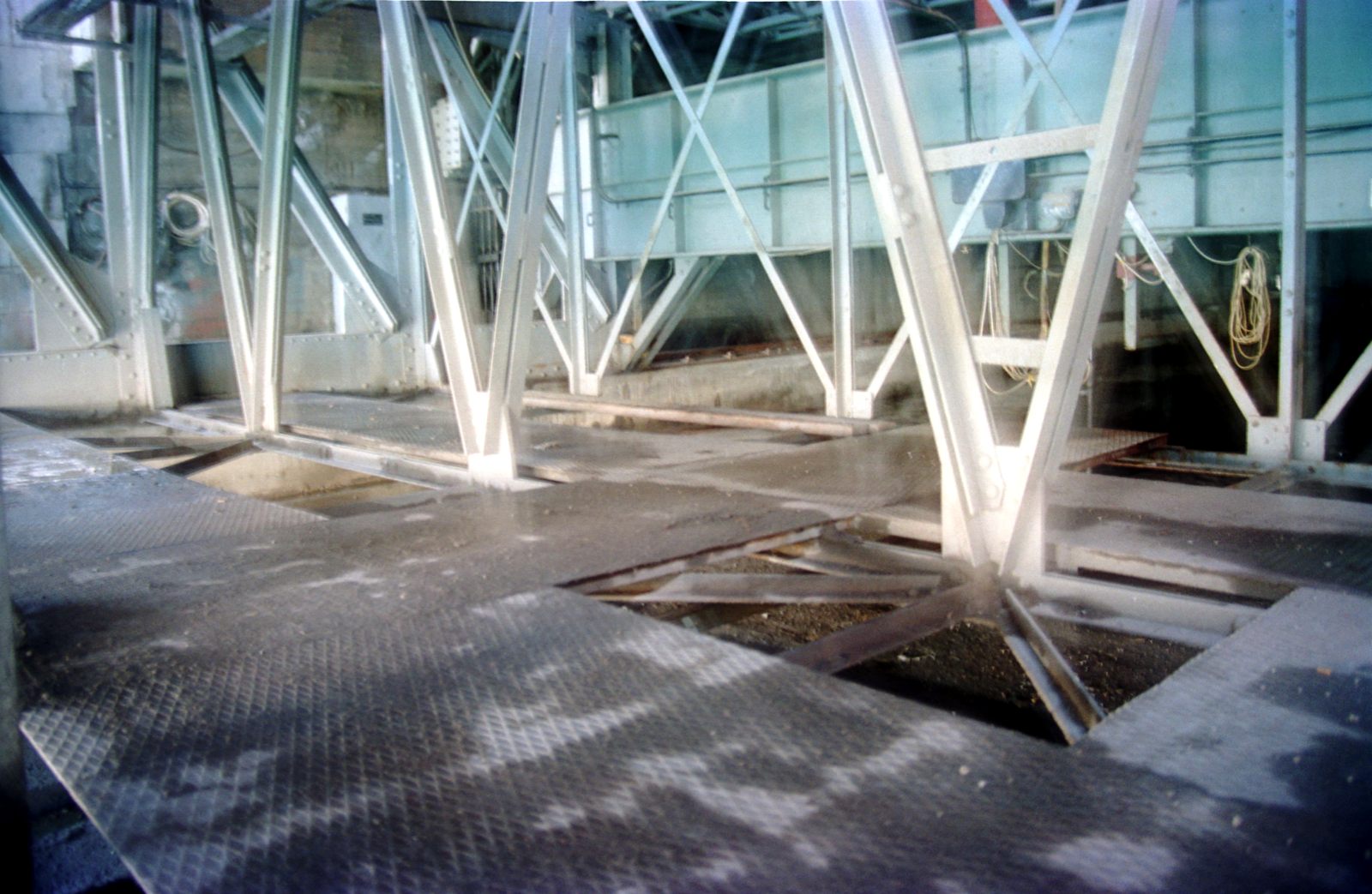
Some also diagonals from the cross trusses, located at the rear section of the tunnel, contributed to this noise by bending, due to their high slenderness while the drainage of bridge had created corrosion issues in the structure.
In the manner described above, "replacing the deck" eventually had led to a substantial renovation of the bridge, not only because of the reinforcements need it after addition the extra permanent load, but due to the necessity to change the structural behavior of the project. Reasons for this was the increased mass of the new deck, the completely different requirements for the behavior of the structure during the anticipated earthquake (zone III, a = 0.24g) and, of course, the intensive use the bridge had, at the time being.
Summarizing (always talking about the structural portion of the bridge):
-
Replaced or reinforced the majority of main truss (cantilevers) diagonals.
-
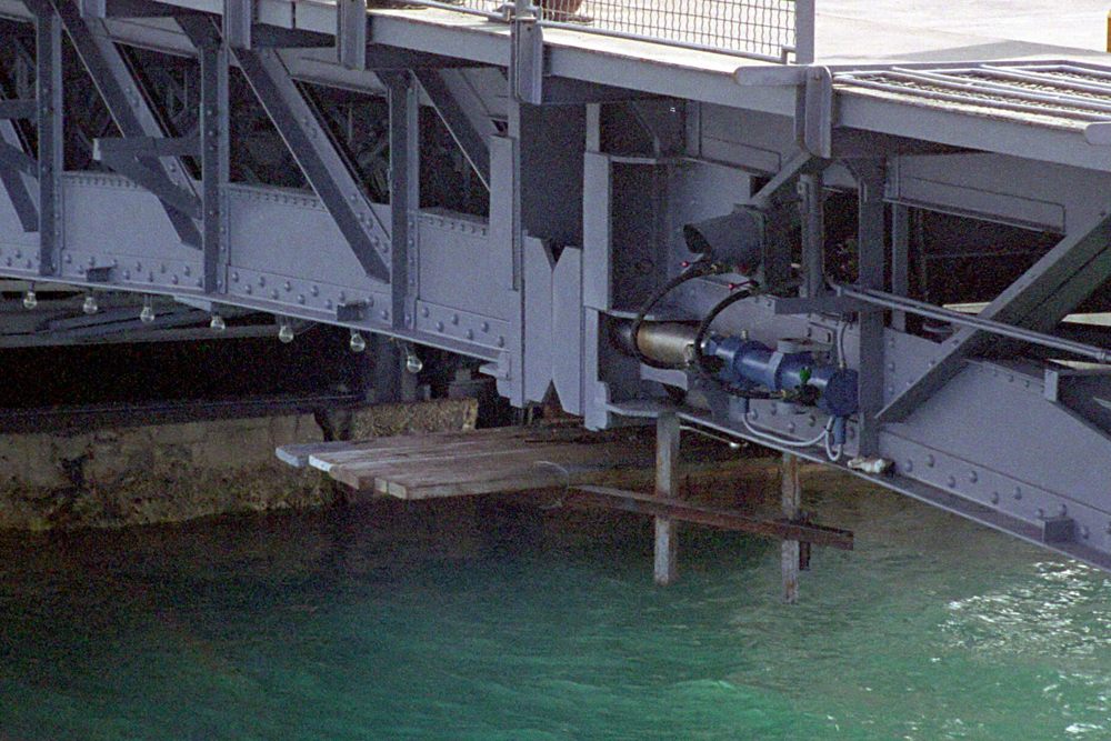
Replaced or changed the bearing the bridge beams during required movement in order to open or close the strait opening.
-
Replaced members in many cross trusses (perpendicular to the main trusses).
-
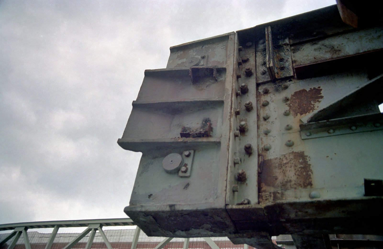
Strengthened top and bottom flanges of the main truss with additional plates.
-
A new horizontal truss was created on top flange of the main truss, below the traffic deck, aiming to carry the horizontal forces (due to wind / earthquake) and to transfer them to clear supports (in the entrance of the tunnel) designed and constructed for this purpose.
In this way it was replaced the existing structure that was serving only as a guide during raising or lowering of the bridge for the procedure of withdrawal or reconnection.
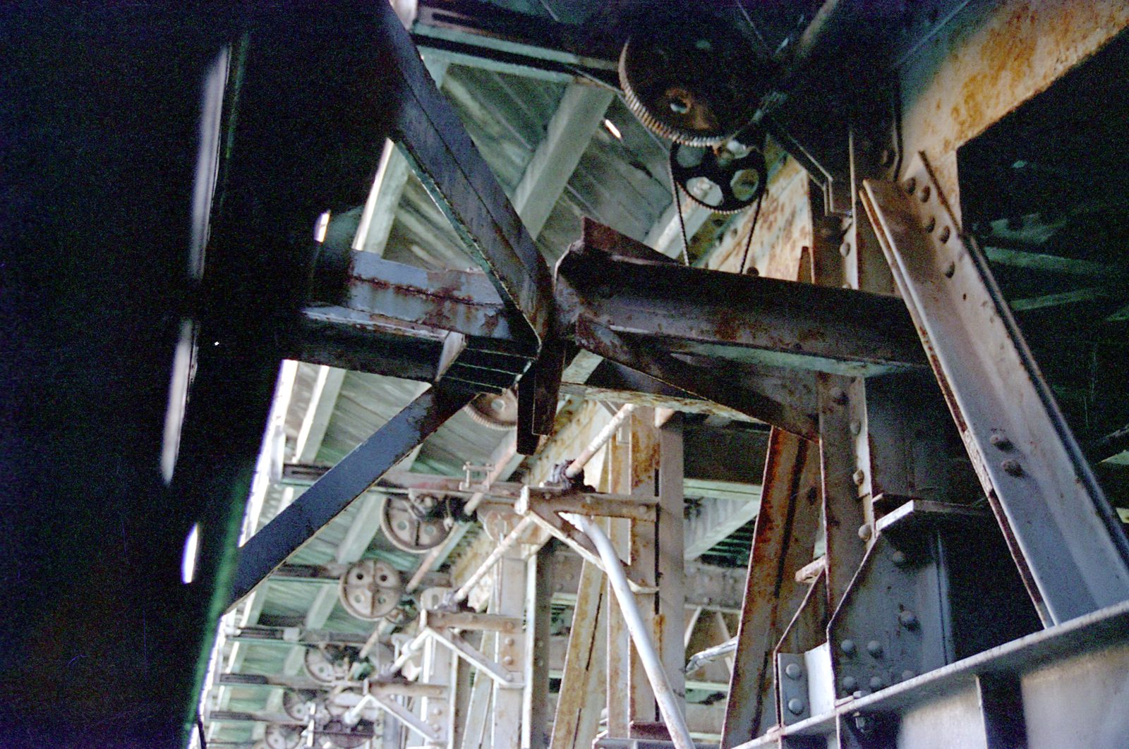
This change also largely increased horizontal stiffness of the bridge thus limiting the respective movement during operation. It should be borne in mind that the horizontal spectral acceleration, to which the project had to be designed, was 0.6g and the existing structure had, until then, only a light truss at the bottom flange, to improve its stability due to buckling. This truss was weak by nature and position to undertake such forces, while the support of any horizontal loads to the ground was done by friction only via the steel blocks on which the lower flange of the main truss was bearing on, when the bridge was taking its final position.
-
On deck added a plate were the asphalt layer had to be placed (by the contract). Ultimately, however, this asphalt layer was agreed to be replaced with the current epoxy material that is in use today.
-
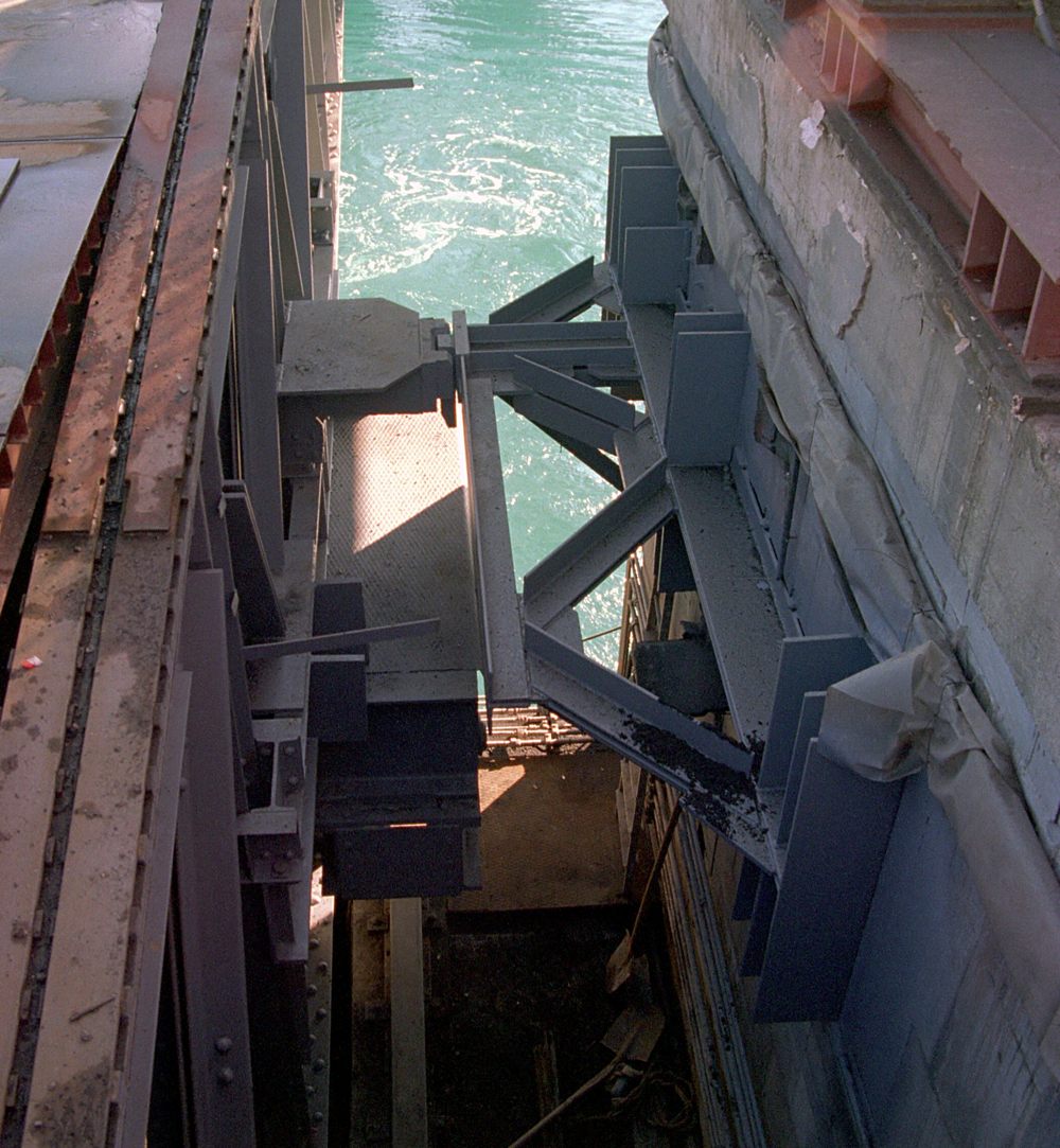
The central links were replaced (those at midspan connecting the two cantilevers).
These links are prototypes designed from scratch with the sole aim to fulfill the needs of the particular project. They consist of two pairs of dowels, rounded at the ends, which are pushed via hydraulically driven jacks into steel pipes with small tolerance so to reduce vibration during operation of the bridge (as explained before).
This link structure had to cope with the large tolerances the bridge would have at the end of its movement, while keeping very small ones during connection, together with the increased horizontal stiffness that now exists due to the new horizontal truss at the upper flange. The fact that these links would carry the heavy traffic loads plus any additional due to the constrain forces, that would develop from tolerances (explained above), forced them to be placed in only certain areas of the main truss.
-
The construction of the bridge project had difficulties due to limited space and of course the claim that was raised to avoid disturbing the city life. In our obligations was to do all shop drawings of the steel members as well as a temporary footbridge 45m long which was placed next to the project and the consulting of the contractor to solve various technical issues.
-
Finally responding to a question posed by the relevant authorities, to measure the reduced sections of steel members due to corrosion and check weldings, force us to review the design calculations. Although there were no significant findings this review used further reduced sections.
Following are presented some of the most descriptive data of the design to better understand the work done for the renovation (again the presentation refers to the structural part of the project).
It is obvious that the word "renovation" describes the scope of the project and not the
unsuitable "repairs" used in the contract, as there was no structural damage (except of the wooden deck) for rehabilitation.
TECHNICAL REPORTS AND STRUCTURAL DESIGN
The first site visit was in September 1995 and the final design was completed in January 1998. Next can be found:
.jpg)

